
Pool sloshing refers to the movement of the free surface of water in swimming pools (or Jacuzzis) and occurs due to the excitation (motions, accelerations etc.) of the yacht. As size and shape of pools have increased in the last years it is important to understand the parameters determining the amount of sloshing. In this paper we describe the different factors and explain that the internal damping of the pool is very important to reduce the amount of sloshing. A novel way of increasing damping of the pool, called Contrawave, is introduced. The system consists of separate chambers at the front and aft of the pool (or port and starboard side of the pool) which are connected to the pool by a slot at the bottom. Above the water level in the chambers there must be an air pocket which is connected by an air duct to the opposing chamber. Here we describe the functioning of the system and the amount of extra damping we have seen from model tests.
1. INTRODUCTION
All modern motor-yachts have a swimming pool and one or several whirlpool baths or hot tubs. The size of pools has increased over the years. Not only in length, but also in width and depth. Yacht designers are very creative in designing areas where the pool is integrated in the total architecture creating a pleasant environment for the owner and guests. The water in pools and hot tubs can start moving (sloshing) due to the motions and accelerations of the yacht. Most commonly these are the yacht motions due to waves, but it could be induced motions due to changes in wind, waves caused by passing boats, anchor chain induced motions etc. Pool sloshing may become problematic if the water motions in the pool are so large that they exceed the freeboard of the pool, causing wet areas and seatings around the pool.
The amount of sloshing depends on different variables. The excitation (the yacht motion amplitude and frequency), the natural period of the pool (or eigen period) and the internal damping of the pool. This will be discussed in more detail in chapter 2.
Problematic sloshing may occur when the pool is excited in one of its eigen periods. If the internal damping of the pool is low, large sloshing motions can occur even with a low excitation. From an operational point of view, it is not desired that the pool water motions are the limiting factor. So, if the other causes of discomfort (yacht motions) are still within acceptable limits, then the pool water’s motion should also be within those limits.
From a design perspective there are multiple factors that can be varied in order to design a good swimming pool. The main dimensions of pools play an important role since they determine the eigen frequencies (resonant conditions) of the pool. In the past, most of the research and papers focused primarily on varying the main dimensions of pools in such a way that yacht motions at pool resonance was avoided. The problem with this approach is that it is greatly limiting the dimensions of pools. Our research has showed that acceptable pool behaviour can be achieved even in resonant conditions with sufficient internal damping.
This paper discusses all these variables, how they influence the pool sloshing and introduces an innovation that can reduce pool sloshing even further by adding a lot of damping.
2. POOLSLOSHING
2.1 Excitation
The movement of the free surface of the water in a swimming pool depends on the ship motions and the accelerations experienced at the swimming pool location. In order to understand the physics, it is important to understand that the velocity of the local water particles in the pool is driven by the local accelerations acting on it. To take into account both the ship’s rotation and the accelerations, the concept of Effective Gravity Angle (EGA) is used. The definition of the (transverse) EGA is given in Figure 1. AY is the transversal acceleration due to the yacht motions at the location of the pool. AZ the vertical acceleration and g the gravity. The local accelerations depend on the acceleration at center of gravity (COG of the yacht) and the angular accelerations times the lever (distance from the yacht’s COG to a given location). This means that the further away from COG the higher the accelerations and thus EGA.

Figure 1: Definition of Effective Gravity Angle (transverse)
The contour plots in Figure 2 show the EGA in longitudinal (left plot) and transversal (right plot) direction. The graphs show the RMS (Root Mean Square) value of the EGA for different wave periods (x-axis) and wave heading (y-axis). Such plots are used in pool sloshing analysis in order to determine the excitation. Ship motion software can be used to derive the relevant information for pool sloshing assessment. At Feadship a tuned version of MARIN’s Q-SHIP is used.
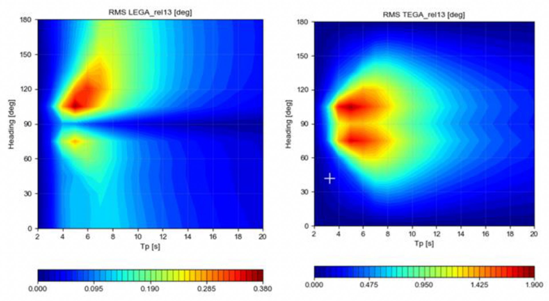

Figure 2: Example contour plots of EGA at pool location for 75m yacht
2.2 Response
Each different swimming pool configuration (not only main dimensions but also shape of the pool) results in different resonance characteristics. Similarly to a pendulum, it will reach its maximum motions when excited in a particular frequency (period). Because pools normally are rectangular in shape, they have a different resonance period in transverse and longitudinal direction. For smaller pools, the first mode (one wave within the pool) is of importance. Larger pools may have a range of resonance modii that become of importance. The largest water motions occur when the yacht is exciting the pool at its resonance. However, large motions can also occur at exciting periods outside the resonance peak of the pool when the exciting motions and accelerations are large enough. High excitation can occur when the natural period of the pool is around the most probable wave periods when at anchor. For the Mediterranean these are periods ranging from 3 to 8 s. In the Caribbean these are between 5 to 12 s. These conditions should not be problematic if the pool has enough internal damping (see next paragraph). From an operational point of view, it is to be avoided that the pool water motions are the limiting factor. In other words, if the normal motions of the yacht due to waves and wind are not limiting then the pool water motions need to remain small.


Figure 3: Example of water motion response with resonance peak
2.3 Damping
The amount of damping in the pool determines the level of the response. If a pool has low damping, small excitations around the resonance of the pool may result in high water motions in the pool. The internal damping of the pool is caused by energy losses in the water due to vortices. Any obstacle in the water can create vortices. A beach is the perfect example of how wave energy is dissipated. The breaking of waves (vortices) dissipates the energy. It is no coincidence that stairs in a pool with the same steepness as a natural beach have the best damping capacity. Drains (vertical or horizontal) also dissipate a lot of energy and consequently generate a lot of damping
For our research Feadship has built a small testing bench (see video below). It consists of a rectangular basin mounted on a table. The basin can be excited in one direction. We can apply a harmonic motion (like a ship motion) with different amplitudes and frequencies. Within the basin we have tested a large amount of pool shapes. Stairs with different steepness, benches, different water depths, drains etc.
The amount of damping due to different pool shapes was determined by measuring the water motions in all these different conditions. The damping is determined in % of critical damping (Bcrit). 100% critical damping means that the water motions are fully damped within one cycle.
A rectangular pool without any internal shape and drains has a 3% Bcrit, which is very low. In such a case, very small excitations will result in high water motions. The resonance results in an amplification factor of the motions of approximately 15. A pool with stairs with a low steepness will have over 50% Bcrit and will thus be able to sustain much higher excitations before the water motions become problematic. The database of shapes with their damping values is used in our design studies for new build projects.
3. POOL DESIGN PROCEDURE
FEADSHIP’s design philosophy is to give the owner and designer a maximum of freedom. For years the advice in designing pools was to avoid resonant conditions. While this is an effective way of avoiding large water motions in pools, it is also limiting the design of pool dimensions considerably. Our yachts have a world wide range and will encounter many different types of seas with different wave periods. Although, FEADSHIP’s yachts are very comfortable, small excitations (so small yacht motions) to the pool may still cause problematic water motions. To not limit pool dimensions, we believe it is more effective to make sure pools have enough internal damping so that if resonant conditions occur they become not problematic. Of course there are limits; a pool over the whole width of a yacht would be a very bad idea indeed. No amount of damping will be able to avoid large quantities of spilling as a small roll angle of the yacht will already make the water go over any freeboard the pool might have. In the discussion with designers our focus is on ways to improve damping and discuss counter measures. To support this discussion and the design the operational profile of the pool in terms of maximum wave heights before spilling occurs is calculated.
3.1 Tools
In our design and engineering procedure we assess the risk of sloshing at several stages (see Figure 5 with our workflow). Depending on the assessment we use tools with different levels of complexity. High fidelity tools or model tests are not needed when there is only a low risk of sloshing. In this way time and money is saved. Recently, various in-house studies were undertaken to identify tools and evaluation methods available. We realized that there was a gap between the low fidelity assessment of pool sloshing and the high fidelity tools like CFD calculations (or model tests). The goal was to have a calculation tool capable of giving good results within a couple of days work. As this was not available on the market, we developed it ourselves.
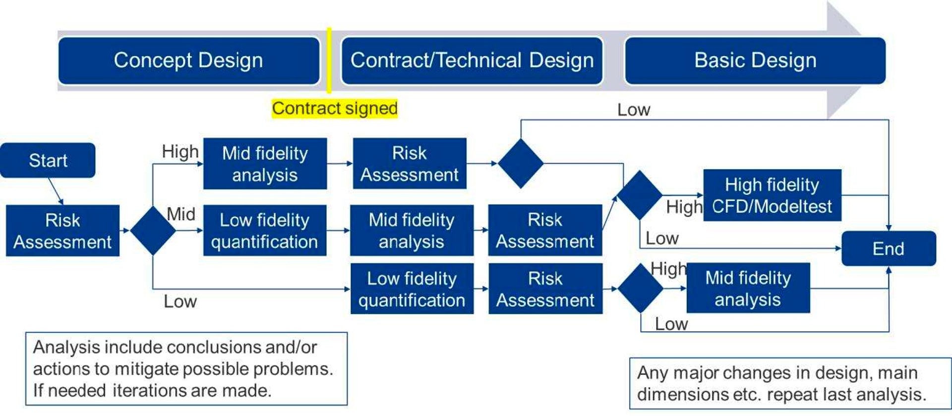

Figure 5: Pool design work flow
In increasing complexity of pool designs, the following tools are used:
3.2 Risk assessment
For the risk assessment we use an excel tool which helps the naval architect to factor in all variables that can influence pool sloshing. These variables are related to the yacht’s dimension, pool location and dimension, pool configuration and things which influence the pool damping. Also, the surroundings of the pool are taken into account as some sloshing is not a problem if the surroundings allow for it. For this assessment experience in yacht motions and pool sloshing is of vital importance. This assessment is therefore only done by experienced naval architects.
3.3 Low fidelity quantification
The method we use is really only an estimation of the pool resonance period modii aka eigen period. Eigen period values do not give an assessment if and how much spilling will occur. But they can however, be used to get a better estimate of the probability of spilling.
Compared to model tests and CFD calculations we have seen up to 15% errors in the estimation of the eigen period for more complex pool shapes. In the design practices this method is used to estimate both the longitudinal and transversal eigen periods. Finally, the pool eigen-period are compared with the characteristics of the yacht (yacht motions in terms of response operator amplitudes RAO) to see if there is excitation around the pool natural period but most importantly also with the wave climate. As explained before if the pool has very low damping small excitations (low motions) may already cause large pool water motions. The wave climate and occurring wave periods where the yacht is sailing are therefore very important.
3.4 Mid fidelity analysis
With the low fidelity quantification, only the natural period of (rectangular) pools can be determined. The method does not give the actual wave height in the pool. Before we did our research the only way to calculate pool water motions for complex pool shapes was via more complex CFD tools or model tests. As this is time consuming and expensive, we developed our own tool which can be used in early design stages. The tool is based on a Boundary Element Method (BEM). BEM is a potential theory method which solves partial differential equations by transforming them into integral equations over the boundary of the domain. Only the water surface and pool walls and bottom are used in the discretization making the 3D problem virtually a 2D problem. The big advantage is reduced computational time. However, this method is limited to solve linear problems. No damping is taken into account. The water motion responses need therefore to be corrected to reflect the internal damping of the pool. We do this in post processing stage.
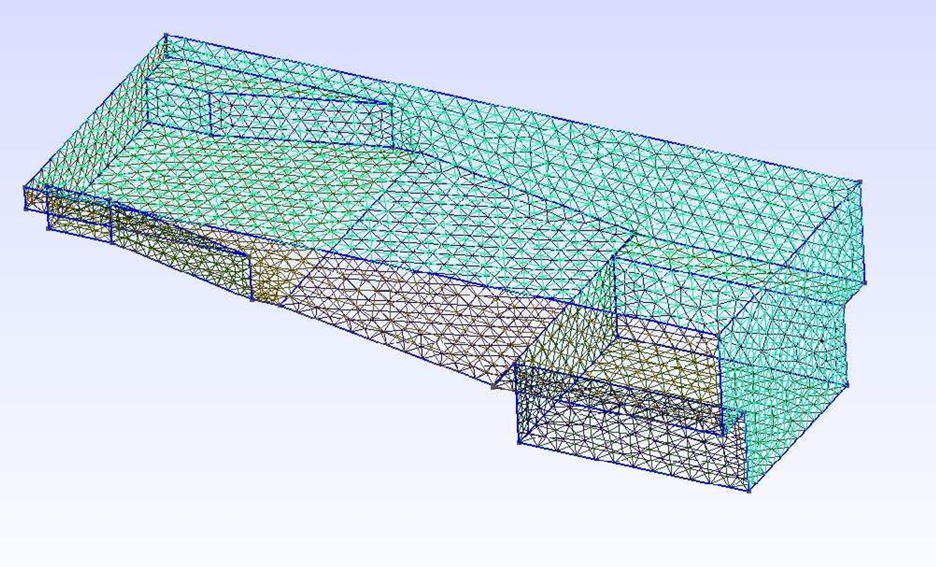

Figure 6: Discretization of complex pool shapes using BEM
The benefits of using this method is a much better estimation of the natural periods of the pool (any shape) and being able to estimate the actual water motions in the pool in terms of response amplitude operators (RAO). Using yacht motions it is then possible to determine the pool water motions in a given sea state.
Figure 7 shows typical results of the eigenmodes calculations. With the BEM tool it is possible to estimate the first mode but also the higher modes in different directions (longitudinal, transversal but also yaw). The results are undamped RAO’s.
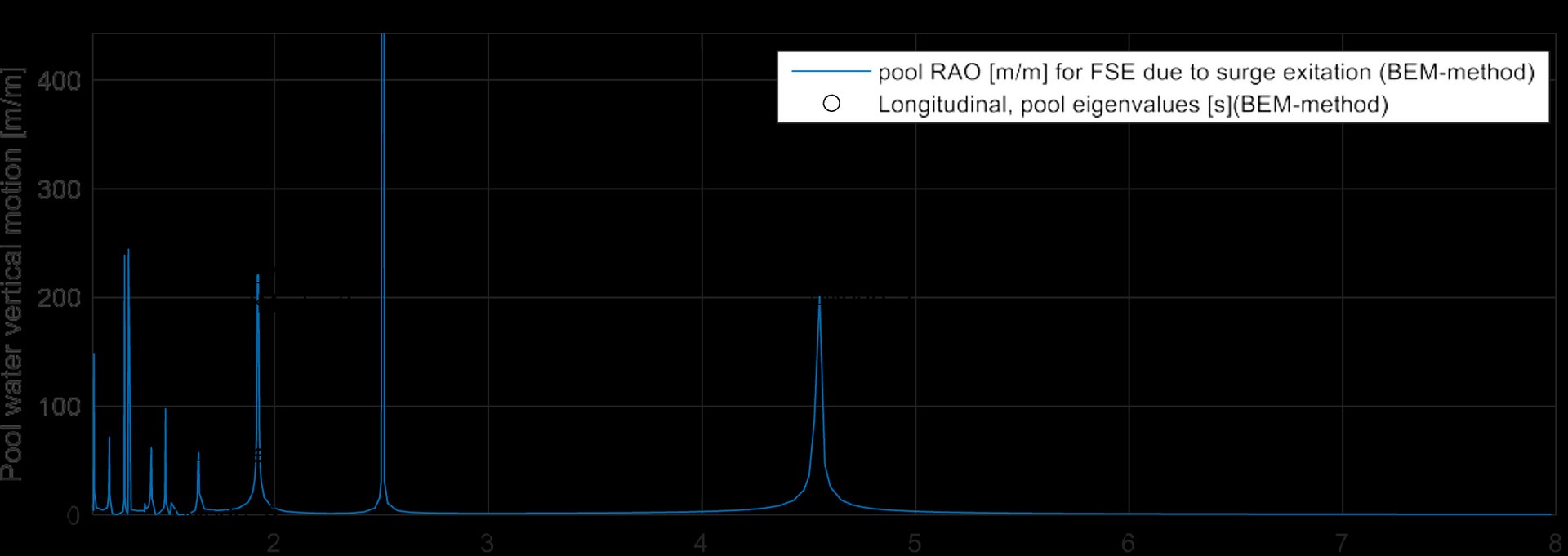

Figure 7: Pool eigen modes
Figure 8 shows the effect of adding damping to the pool water elevation RAO. In order to apply the correct amount of damping, use is made of the pool shapes damping experience database from the in-house damping principle tests. The amount of damping is deducted from this parametric variation and we are able to apply the correct amount of damping for new pool designs.


Figure 8: Effect of damping on pool RAO
Figure 9 shows an example of the tuning of the damping and comparison with model test data. The damping from the Feadship pool shape damping experience database has been used.
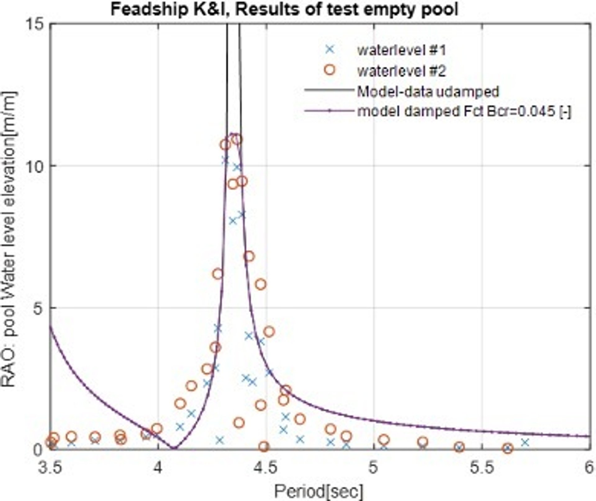

Figure 9: Validation of BEM method using model test data
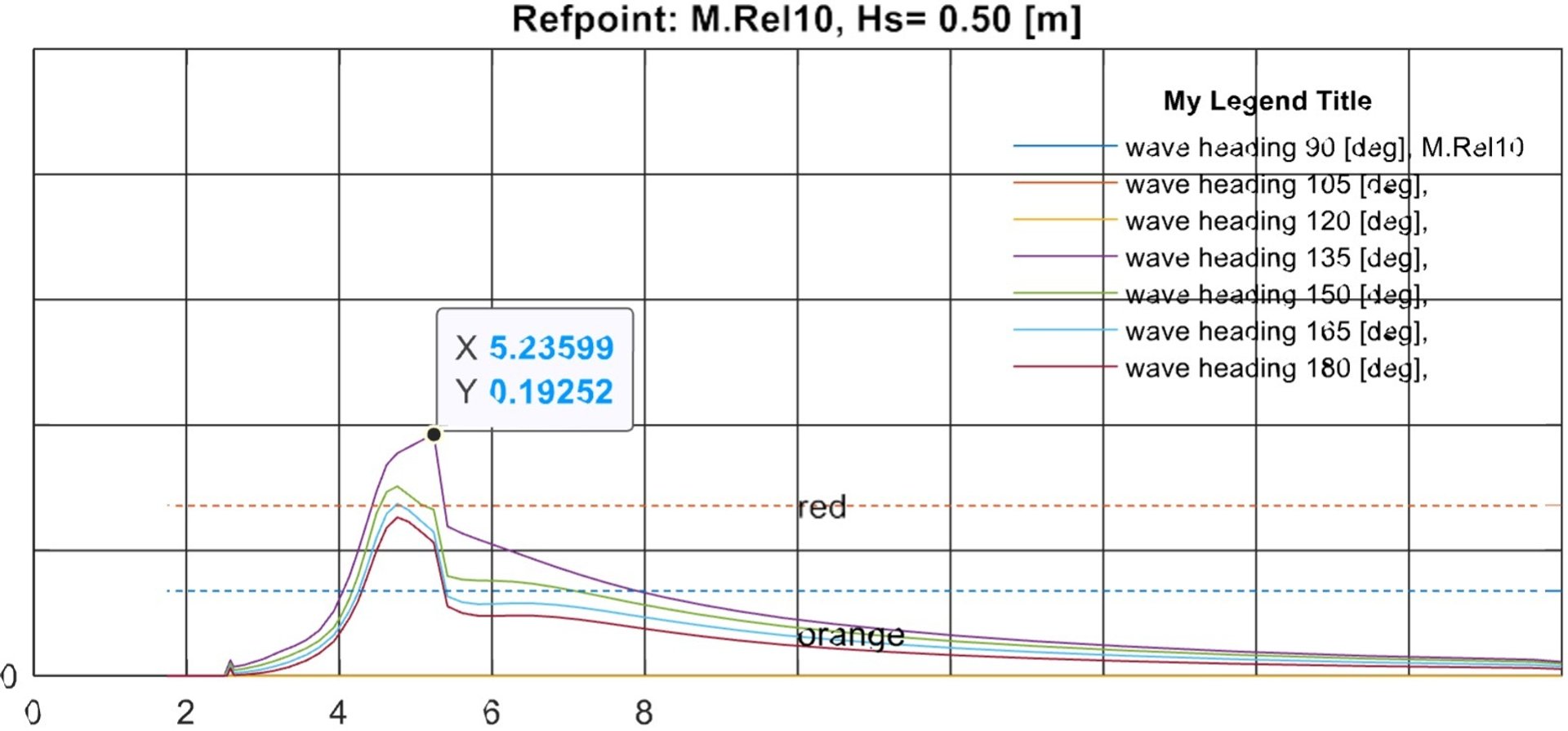
With the tuned RAO’s of the water elevation it is possible to determine the water motions in the pool for an actual sea state. The yacht motions need to be calculated for that. The results can be presented like shown in Figure 11 where the most probable maximum of the water elevation is given for one wave height and several wave headings and wave periods. In this case the highest dashed horizontal line (marked red line) is the freeboard of the pool construction above the water level. If the MPM value is above this line, it means that the water will spill over the pool.

The BEM tool has been used for the last two years successfully for new builds. Based on the results we are able to improve the pool design and give insight to the crew in which conditions spilling might occur.
3.5 High fidelity calculations / model test
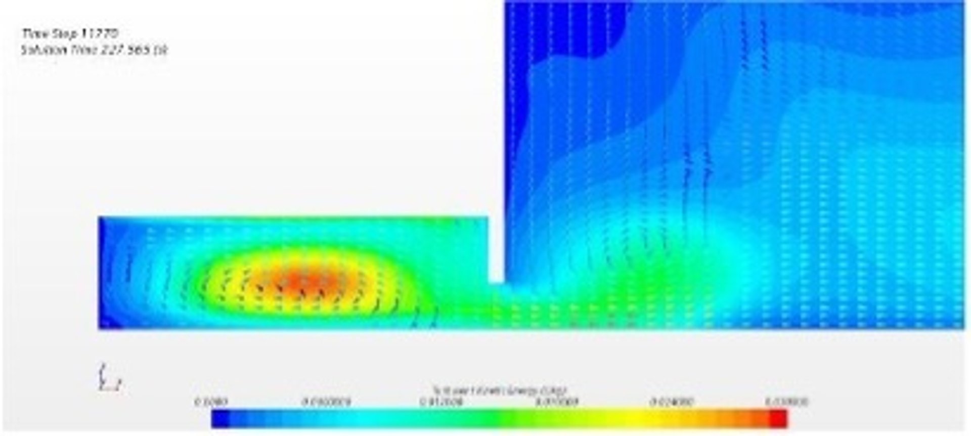
For high risk designs or pool configurations for which there is no experience yet, it is wise to do CFD calculations (see for example Figure 11) and or model tests [Ref 1] (see Figure 10). These are time consuming and expensive so preferably they are done in a stage where the yacht design is fixed (otherwise the yacht motions could be off) but there is still some room to improve the pool design if needed.
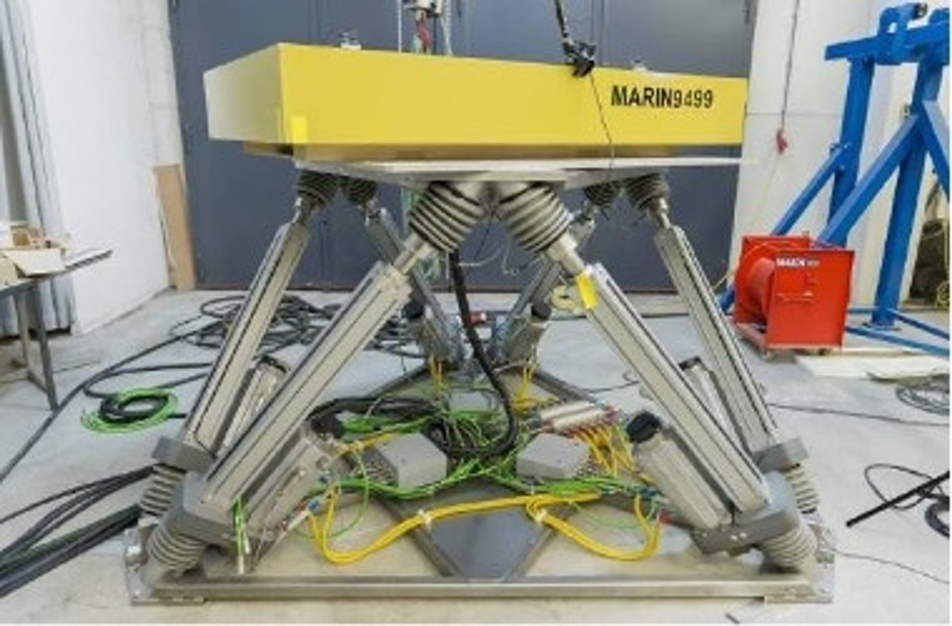

Figure 11: CFD analysis of the Contrawave system

4. CONTRAWAVE
Besides investigating the damping due to the obvious shapes (stairs, benches, beaches etc.) research has been doon for novel ways of adding damping to the pool to minimize pool sloshing. The design criteria used for the development of these systems are: low complexity, no moving parts, low or no energy demand and low costs. Most importantly, the aesthetics and design freedom of the yacht should not be compromised.
After several iterations in the last 4 years the development of a system which fulfills these criteria and improves the damping of the pool has been successfully finalized. A patent of the system which is named CONTRAWAVE is currently under review. The system consists of chambers at the aft and fore of the pool. These chambers are connected to the pool by a slot at the bottom of the pool. Above the water level in the chambers are air pockets. The air pockets of both the chambers are connected with each other by means of an air duct. If needed, a static amount of air pressure can be used to create a larger amount of air. While the water in the pool will start to move due to yacht motions the water and air in the chambers will also start to move. By carefully designing the amount of water and air in the chambers as well as the height of the connecting slot and the diameter of the air connections, the water motion in the chamber can be tuned so that it will counteract the motions in the pool. The system adds also damping due to the slots at the bottom of the pool (vortices in the water while it flows in and out of the slots), but the majority of the damping comes from the tuning of the water motions. The chambers used in the Contrawave system resembles the chambers used in wave making systems in commercial land-based pools but have of course a different purpose. Comparable systems (u shaped ducts to damp water motions in a tank) have been researched for other purposes than swimming pools. The work performed by Hayama and Inoue [Ref 2] has been very valuable to develop our system and to understand the physics behind it.
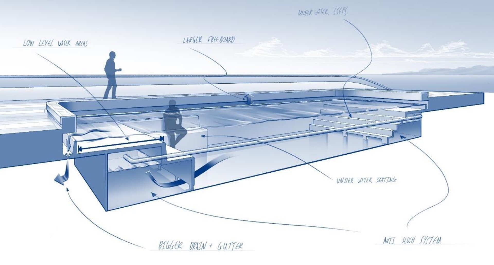
In Figure 12 a sketch (not to scale) is given of the Contrawave system. The figure also gives other ways to improve damping in a pool. In this sketch the chambers are located below the water level in the pool so extra (static) air pressure needs to be applied to create an air pocket. In the examples given here the air chambers are located at aft and fore of the yacht. We have seen that in normal operational conditions in combination with the rectangular shape of pools the longitudinal motions (pitch in combination with yaw) are often the cause of sloshing. In those cases the aft and fore chambers are preferred. In other configurations, where transverse motions could cause sloshing, chambers at port and starboard could be used.


Figure 12: Pool design help with sketch of Contrawave system
In order to test and validate the system extensive BEM and CFD calculations have been performed. The system has been also tested on two occasions at the Maritime Research Institute (MARIN). In Figure 13 results of a model test time series of the wave height at the edge (fore) of a pool are given. The figure shows the wave elevation with and without the Contrawave system in regular waves. In this case the system reduces the wave height by 75%. For these tests the base case was a rectangular pool without any other damping increasing measures. If the pool already has benches, beaches etc. reductions of about 30% are to be expected, which are still significant.
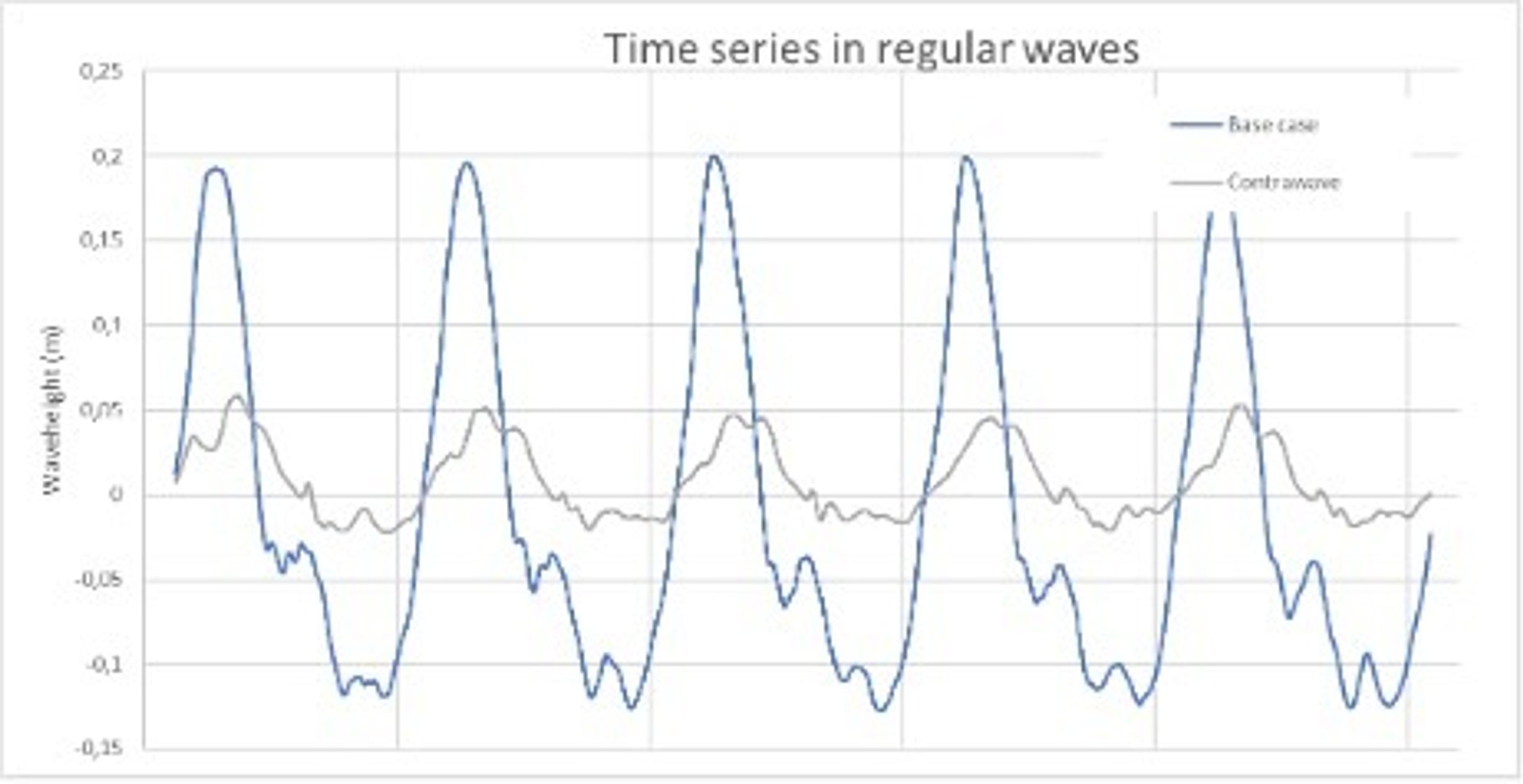

Figure 13: Model tests with and without Contrawave
As no pool or yacht is the same, the system needs to be designed on a case by case basis. The dimensions of the slots, chambers and air ducts need to be carefully calculated for optimum results. The experience and tools that have been developed are crucial in achieving this. The system is actively promoted in our new build contracts. The first installation of the system can be expected in the coming years.
5. CONCLUSION
The complexity of the pool sloshing phenomenon is a hydromechanics dream if you like challenges. The wave climate, response of the yacht to it and the excitation of the yacht on the pool makes it a very complex problem indeed. As yachts operate in mild conditions (yachts seek shelter as soon as mild discomfort of passengers may occur) problematic pool sloshing occurs when there is a large amount of sloshing exceeding the freeboard while the yacht is not noticeably moving. This may occur when the small yacht motions excite the pool at pool resonant conditions and the pool has low damping. In our designs Feadship’s objective is to give the client and designer maximum freedom by avoiding limiting the pool dimensions and seeking other solutions to avoid problematic sloshing. The research performed on the parametric variation of pool shapes has given us the required valuable knowledge..
A computational tool based on Boundary Element Method (BEM) is capable of calculating with a higher accuracy the pool resonant frequencies than the formula for rectangular shaped pools. With a correction for the internal damping of the pool; the tool is capable of calculating the actual water elevation and proved a valuable tool in early design. The main advantages are time and costs compared to full 3D CFD methods. A novel system (Contrawave) for which a patent is pending was researched and developed. It can add a large amount of damping for pools to minimize sloshing.