
Part of Feadship’s strategy is to research any potential energy and power system that might become relevant both in the short and long term. Nuclear power is certainly a relevant source of energy for large-scale shore-based grid applications. However, shipboard implementations, especially in privately operated applications, have yet to be realized. Various social, legislative and technical challenges hinder applications onboard superyachts in the foreseeable future. Nevertheless, technical and conceptual investigations are relevant.
This paper presents a high level and applied perspective on the implications of onboard nuclear power systems and trades off the viability in comparison to grid-based nuclear power systems. The paper overviews the relevant nuclear technology developments distinguishing various generations for shipboard and grid-based applications. It identifies the main system components for a shipboard application and sizes these for relevant yacht powering concepts.
1. Nuclear technology development
In this chapter the state-of-the-art of nuclear technologies is covered, Different generations of nuclear technologies are overviewed (section 2.1). Relevancy for grid-based (section 2.3) and shipboard (section 2.2) applications are further considered.
1.1 Generations of nuclear reactors
A main distinction of nuclear reactors is by generation as indicative of their state of the art. In principle, generation I, II, III/III+ and IV are distinguished. The first commercially operating reactors were generation I reactors, dating 1950s and providing up to 50 MWe [1] [2], [3]. In 1970s generation II reactors started being deployed, representing most of the reactors used nowadays. Their competitiveness was achieved via economics of scale with installed power of 800-1500 MWe, higher than the first-generation designs [1]. Generation II reactors are designed for 30-40 years operations, extendible up to 50-60 years [1] [3]. The majority of the nuclear power plants used today are based on Pressurized Water Reactors (PWRs) and Boiling Water Reactors’ (BWRs) generation II technologies [1] [4]. As an evolution of generation II reactors, generation III/III+ technologies started being deployed in 1990s. These aim at increasing efficiency, lifetime and safety while reducing costs. Significant design changes followed the accidents of Chernobyl in 1986 and Fukushima in 2011. Favourable characteristics of third-generation plants are associated to the core damage in case of extreme events. As a result of various added safety features the probability of core melting accidents is further reduced than generation II designs. Additional benefit is reduced waste due to higher fuel burnup [5]. Typical examples of third-generation reactors are the European Pressurized Reactor (EPR) and the Advanced Boiling Water Reactor (ABWR), which are advancements of the PWR and the BWR respectively [1] [2] [4]. Other designs encompass heavy water reactors, HTGR and FNR [5]. In perspective, generation IV designs are envisaged to be deployed after 2030 as indicated by the Generation IV International Forum (GIF). These reactors aim at sustainability, safety and reliability, economics, and proliferation resistance and physical protection. As well as higher power density, use of non-water coolants, high temperature operations and integration with production plants [2]. Goals and requirements of these reactors are listed in Table 1A in appendix. The generation IV reactors identified by GIF are GFR, LFR, MSR, SFR, SCWR and VHTR [2]. A more complete overview of these reactors is given in Table 1B in appendix. LFR, GFR, MSFR, MSR and VHTR can be deployed for hydrogen generation. Some can operate only for hydrogen synthesis or in a co-generation scenario [6].
In addition to the mentioned designs, nowadays there is a shared interest in developing small and modular units to provide electricity and process heat. This enables mobile use, and drop of production, transportation and installation costs [7], [8], [9]. An additional feature is passive safety, thus less reliance on external power in case of severe accidents. Moreover, these reactors can be stored underground or underwater. Refuelling is done around every 10 years [7]. These designs can be categorized on the output power: medium modular reactors are ranged 300-700 MWe, small modular reactors (SMRs) provide between 15-300 MWe and very small (or micro) modular reactors (vSMRs/MMRs) have an output power equal or below 10-15 MWe [7], [8]. The first commercial reactors were deployed in the late 1950s and 1960s and were based on LWRs. They can be considered as scaled-up versions of naval propulsion reactors. Nevertheless, although small reactors were used in the past, the new designs are not commercially viable yet. The main challenges that they are facing today lie not only in their smaller size but in the new safety features and business cases [8].
1.2 Nuclear options for shipboard applications
For selecting the nuclear technology type for application in yachts, some criteria are identified. Generally, the selection is primarily influenced by the reactor power output to fulfil the yacht’s operational profile. Estimated required installed power is in the range of 2-15MWe from small to large superyachts. Consequently, MMRs are identified as the most suitable power range category for onboard installations.
Alongside the power range, important criteria encompass:
- Load-following and system start-up: continuous system operation is to be guaranteed, managing power fluctuations from low base-load (2-5% of installed power) to propulsion load (30-100% of installed power).
- Passive safety: in case of failures, the decay heat generated by decay of radionuclides needs to be removed from the reactor location and transferred to the external atmosphere.
- Modular and self-regulating design: these features lead to off-site factory fabrication, cost reduction and low maintenance.
- Proliferation resistance: prevents diversion of weapons-usable material.
- No emissions and no noise pollution: cutting the emissions is the main goal of investigating nuclear propulsion, while a silent reactor guarantees comfort onboard.
The selected MMRs meet the requirements of passive safety, modularity and self-regulation. Passive safety is achieved via the use of coolants and fuels with negative temperature coefficients [10]. Furthermore, some designs, namely heatpipe reactors, harness sodium as working fluid allowing for natural convection for heat removal in case of failures [1], [11], [12]. Reactivity and therefore power output is automatically controlled via control rods [10] or drums [11] depending on the technology type. Lastly, the limited noise pollution is achieved with the limited-to-no use of moving parts [11], [13].
1.3 Nuclear power for marine e-fuels production
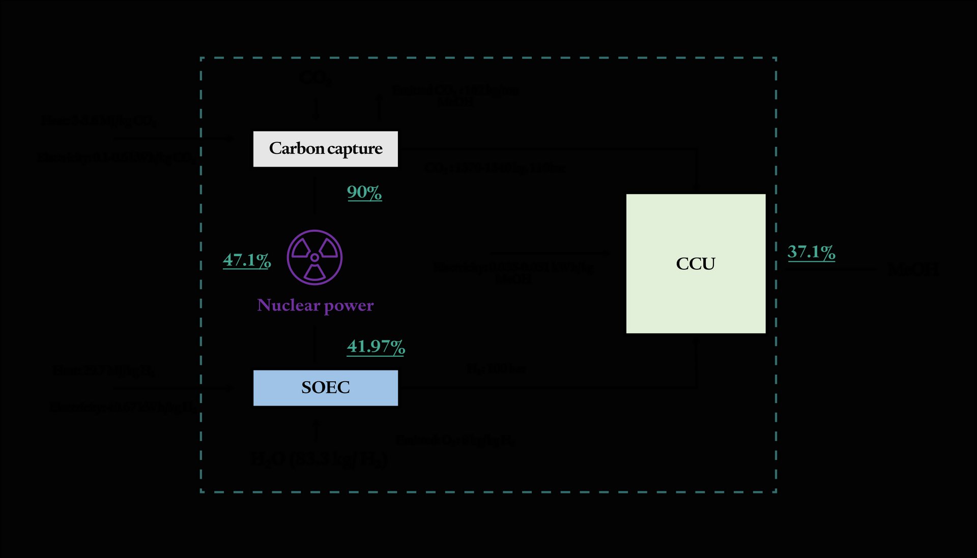
A perhaps more logical use of nuclear power is to produce e-fuels as hydrogen, ammonia, methanol, and paraffinic fuels (e.g. diesel, kerosene). Liquid fuels, such as diesel and methanol, can be easily used on superyachts via combustion engines and fuel cells, providing a scalable pathway to indirectly power yachts with nuclear energy.
As for methanol production, hydrogen is to be produced first. The ideal free-carbon option for this is the water electrolysis method [10] with high-temperature steam electrolysis (HTSE) identified as the most promising method for its relatively high efficiency, high technology readiness level (TRL) and low production costs [11], [12], [13]. For this, the nuclear plant has to match the scaled-up hydrogen facility and the reactors need to work at constant high temperatures and low pressures to respectively secure dissociation reactions and avoid that these would reverse [14]. Contamination by tritium is to be avoided [1], [14]. Generation IV reactors fulfilling these criteria are identified by GIF and reported in Table 1B in appendix [2], [6]. Specifically, (V)HTRs and MSRs/MSFRs best perform among generation IV reactors [15]. These reactors can be installed both onshore and as floating nuclear power plants (FNPPs). FNPPs can overcome land distribution issues, alleviate safety concerns and sea water can be used as a coolant. FNPPs can be docked in harbour or within the exclusive economic zone. For offshore installations, generation IV reactors benefit from a highly shared interest from various industries. MSRs have been largely investigated by companies like CorePower [16] and Seaborg [17] for hydrogen/ammonia co-generation.
For conceptual comparison, the efficiency of a nuclear-produced methanol fuelling an internal combustion engine (ICE) was calculated and compared to a nuclear system onboard. The two systems are considered providing the same power output for a 2500 GT yacht. Calculations are reported in appendix 7.3 and 7.4. Results for the required methanol energy content are presented in Table 4.
Table 4: Feedstocks and electricity required for nuclear-based methanol production for a 2500GT yacht
| Parameter | Unit | Value |
|---|---|---|
| H2 needed | [t] | 43.8 |
| CO2 needed | [t] | 320.9 |
| Electricity inputSOEC | [MWh] | 1779.7 |
| Heat input SOEC | [GJ] | 1299.7 |
| Electricity input CCU | [MWh] | 11.9 |
| Total electricity consumption for MeOH production | [GWh] | 2 |
| Total nuclearelectric power to install for MeOH production | [GWh] | 13.5 |
| Methanol energycontent | [GWh] | 1.3 |
The efficiency of the methanol production from nuclear power plants was calculated as per appendix 7.4. Results are given in Figure 1 showing the efficiency for installed HTGRs onboard a 2500 GT yacht and the efficiency of a nuclear-produced methanol propulsion. The onboard reactors refer to two designs from literature as explained in appendix 7.4. There is quite a large difference between the efficiency of a MeOH deployment and direct nuclear propulsion. This is due to the energy losses of the production given the several steps leading to methanol as a final product. The uranium needed to produce the required methanol for the yacht is 5 to 9 times higher than the one used by a reactor onboard. Therefore, direct nuclear propulsion reduces the use of the fissile material substantially, however economic benefits associated with the high-power utilization of the on-land or near-shore grid-based applications can be considered. For instance, a nuclear power system onboard a superyacht can expected to be used for 5-10% yearly time, whereas a reactor connected to the grid can have annual utilization of 100%, yielding higher return on investment.
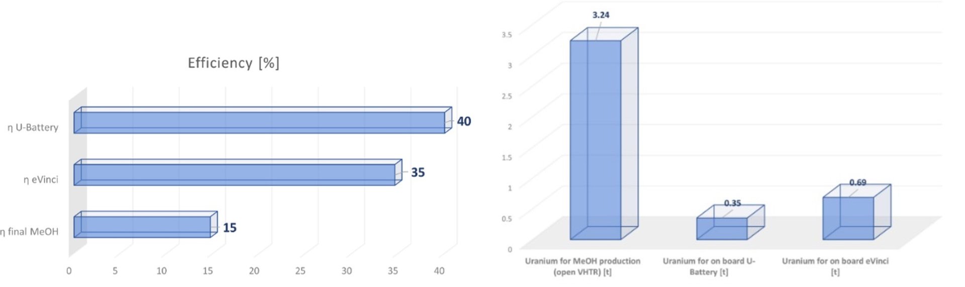

Figure 1: Efficiency and fuel use
2. Shipboard intergration of nuclear reactors
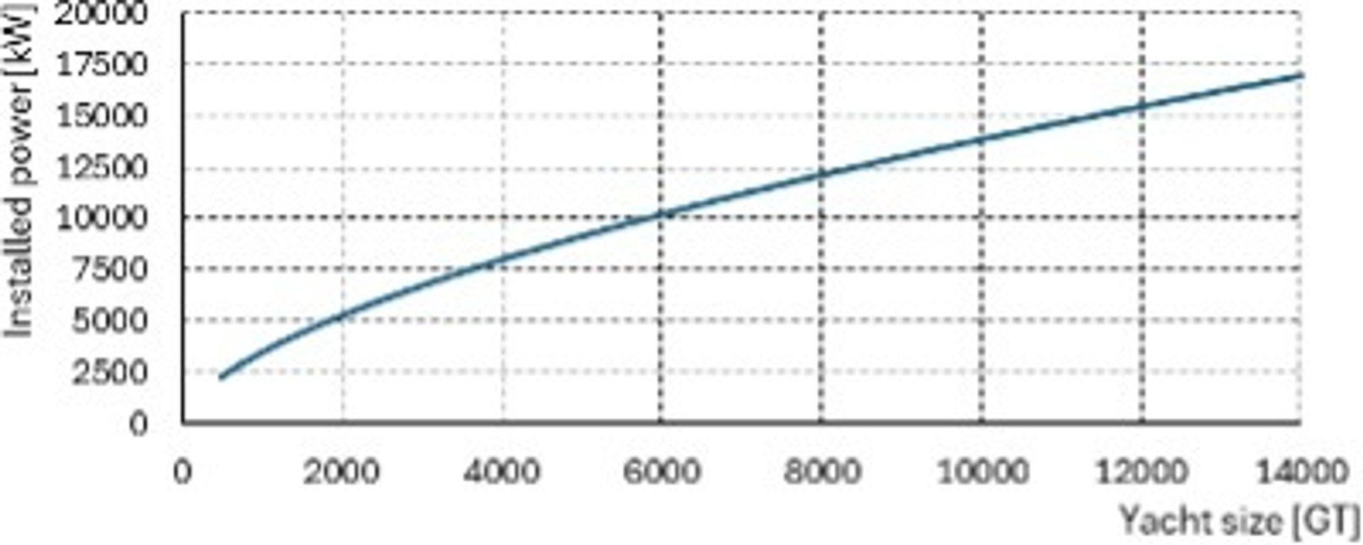
In this chapter the integration of MMRs (section 2.2) onboard yachts is presented. As highlighted in section 2.2 the yacht’s power demand is the main criterion driving the reactor’s selection. For this study a design trend was determined based on the Feadship fleet shown in Figure 2:. There, the installed power is depicted against the yacht’s size. A typical associated load profile is 90% of time operating at 5% of installed power, 9.5% of time at 33% of power and 0.5% of all time at 100% power. Selected designs are U-Battery by Urenco, TU Delft & UK partners and eVinci by Westinghouse. As Table 2A shows, U-Battery is a high-temperature gas reactor (HTGR) whilst eVinci is a heatpipe (HP) reactor. In the following sections these two technologies are presented. Next, their installation onboard yachts is covered.

2.1 High-temperature gas-cooled reactors
Figure 3 depicts an overview of a high-temperature gas-cooled reactor (HTGR). These designs are helium-cooled reactors although nitrogen can be used as a secondary coolant [6], [9], [18]. Graphite acts as moderator and reflector surrounding the core enclosed in a steel pressure vessel [6], [18]. The fuel is low enriched UO2, while thorium might represent an alternative in the future [18], [9]. The fuel particles have a TRISO geometry, encompassing a kernel of 235U surrounded by carbon and silicon carbide layers [6], [18]. The TRISO geometry reduces the risk of fission products release, while the inert nature of helium avoids explosive gas generation or phase change [18]. A new approach to fuel-related safety is given by the TRISO particles encapsulated in a SiC matrix. This technology developed by USNC is called Fully Ceramic Micro-encapsulated (FCM) Fuel. It is resistant to radiation and thermal damage and keeps the coolant extremely clean and improves tolerance of air and water ingress compared to old graphite pellets [19]. Typical operating temperature of the HTRGs is 750-850 °C [20], [9]. Either Brayton or Rankine cycles can be deployed for electricity generation [6], [9], [7]. The reactor depicted in Figure 1 consists of a direct Brayton cycle with helium driving a gas turbine and no intermediate loop [21].
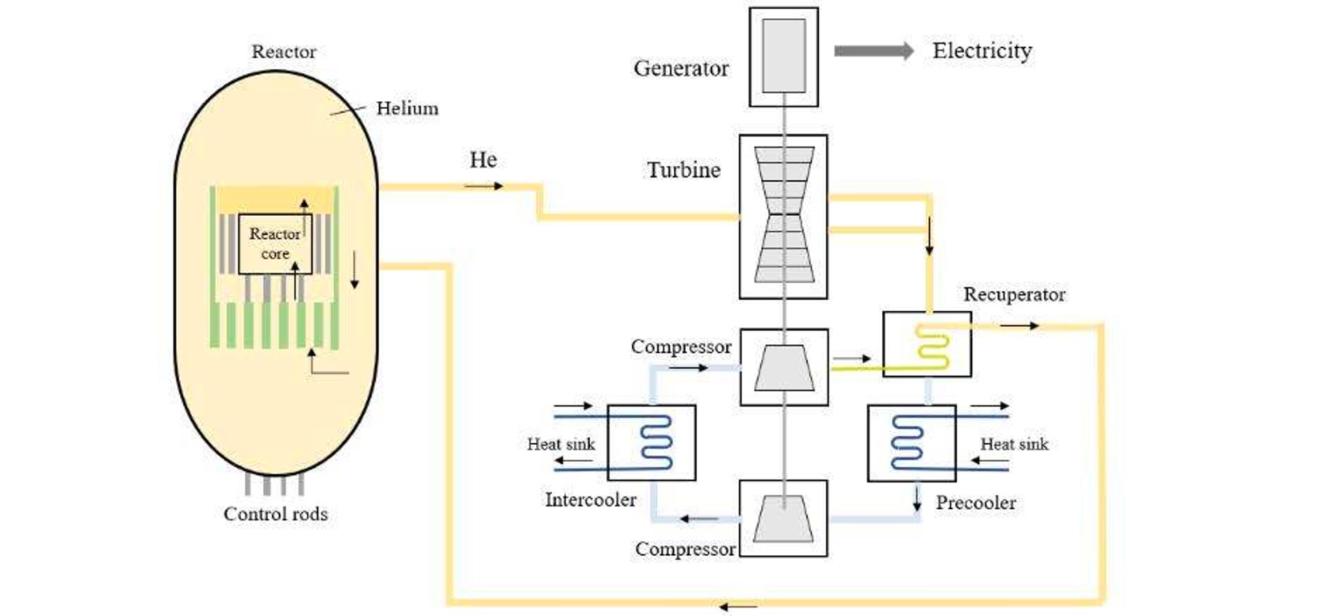

Figure 3: Overview of a high-temperature gas-cooled reactor [22]
2.2 Heatpipe reactors
Heatpipe (HP) reactors differ from conventional nuclear reactors in several aspects. HP are compact solutions which started being developed for deep space and military basis [23]. Conventional nuclear reactors use a fluid (gas, liquid metal, water, salt) to extract heat from the core and transfer it out to a working fluid [24]. In HP reactors the working fluid is contained in each sealed pipe. This transfers the fission heat from an in-core evaporator to an ex-core condenser region [23]. The operating temperatures of these reactors is 650-1000°C [24].
Figure 4 (right) depicts the basic working principle of a heat pipe. The left-side of the heat pipe in the figure, where the evaporator area is indicated, is embedded into the core where the nuclear fuel roads are inserted. These enter the heat pipe and consequently the working fluid circulates towards the right side where the heat is captured by the primary heat exchanger [25]. The condenser contains heat exchangers for electricity generation and decay heat removal [23]. Figure 4 (left) shows a configuration with a primary heat exchanger and a decay heat exchanger. The former extracts heat from the core and convert it to electricity, while the second heat exchanger removes decay heat in emergency situations [24]. The working fluid keeps travelling up a wick, made of a microporous metal, and goes back to the left side [25].
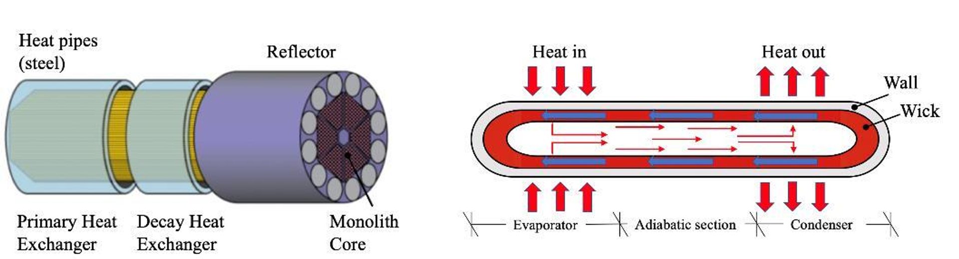

Figure 4: Illustration of heatpipe reactor (left) and heat pipe principle (right) [23], [24]
Fuel rods are located in the core, which comes as a monolithic solid block containing the heat pipes, whilst the heat pipes are located on the periphery and welded together with the fuel rods. From the heat pipe basic principles description, it emerges that the heat transfer is completely passive. Similarly to conventional reactors, HPs use LEU fuel to prevent proliferation [1]. Identified fuel materials are UN, UO2, UZrH and UMo. The reactivity of the LEU is controlled through Doppler effect and control drums. A control drum consists of a rotating cylinder inserted within the reflector, the latter with Beryllium (Be or BeO) material. Typical reflector materials are Be, BeO and graphite [23]. Power can be converted via free-piston Stirling or Brayton cycle. A recuperating heat exchanger can be installed to improve the cycle performance [23], [9].
2.3 System schematic
In this section the system schematic is presented for nuclear propulsion for both HTGR and HP reactors. An electric turbine propulsion is common to both designs, and it is integrated with a battery pack. A battery system is installed to cope with power demand fluctuations which can be the case of manoeuvring. Westinghouse tested an integration of the eVinci with batteries leading to a response time in the milliseconds range [25]. Same considerations can be applied to the U-Battery design following discussions with experts.
Regarding the power conversion unit, starting with the eVinci, this design encompasses an open-air Brayton cycle, as shown in Figure 5. This consists of a single shaft turbomachinery made up of a compressor, turbine and an alternator [9]. An air filter is installed to filter the air entering the compressor. The plant does not require a condenser or a heat exchanger for cooling, while the used air is simply rejected. In fact, the primary and decay heat exchangers are integrated in the reactor unit as being part of the HP design. Cooling of waste heat is done through seawater.
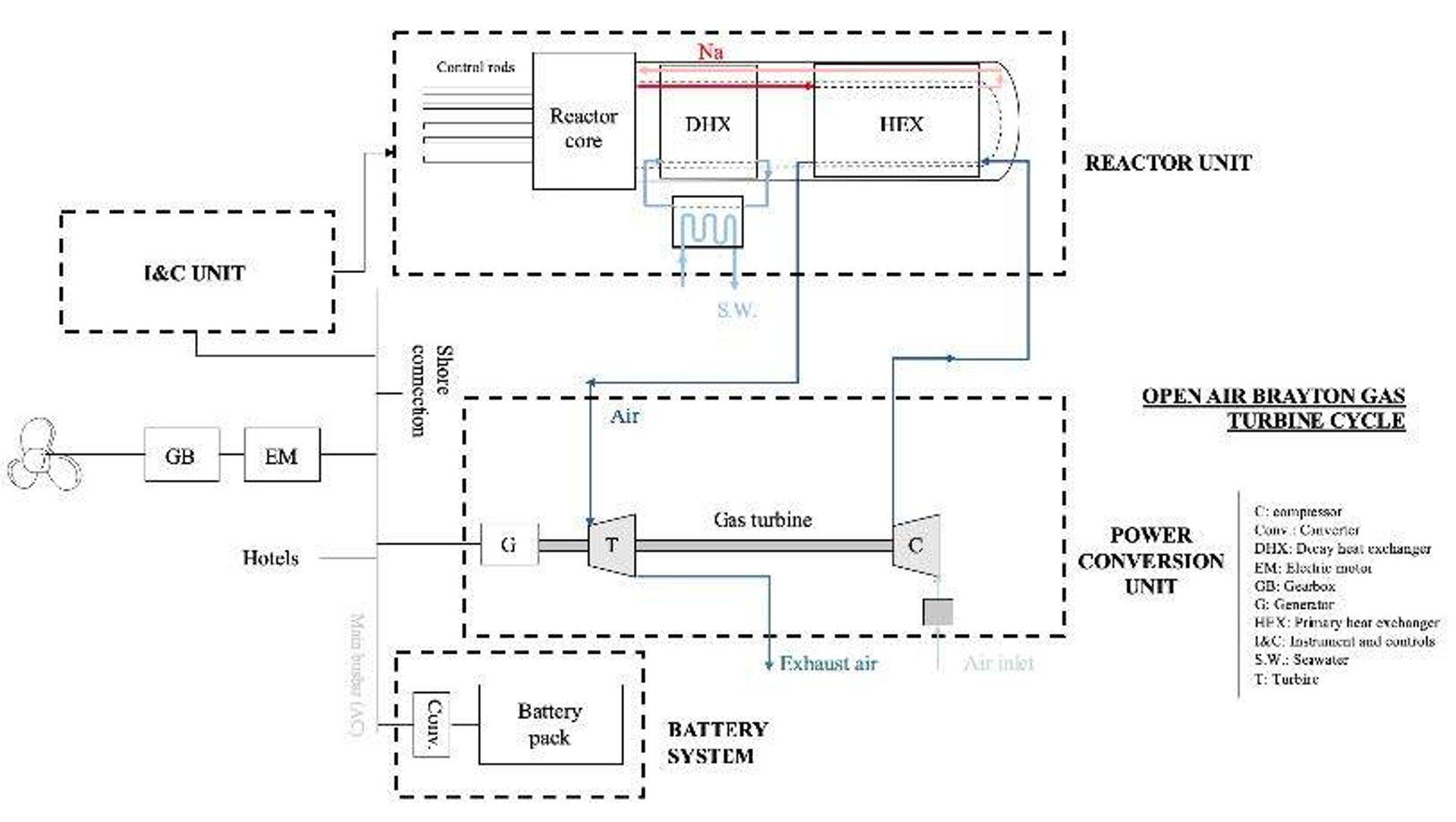

Figure 5: eVinci system layout, based on [9], [26], [25]
Regarding the U-Battery design system integration, a schematic is given in Figure 6. For this, an indirect gas-turbine is installed, with no combustion stage and employing a closed-cycle design. Alternative solutions to an indirect gas-turbine are possible, namely: direct/indirect steam (Rankine) cycle; a direct CO2 turbine; or direct thermal-to-electrical conversion, and Alkali-Metal Thermal-to-electrical conversion (AMTEC). However, disadvantages associated to low reliability and efficiency, and high maintenance and system complexity are to be considered [9], [27], [28]. Next to an indirect gas-turbine a circulator is installed to recover the pressure drop at the intermediate heat exchanger outlet increasing it for the reactor inlet [28]. A recuperator recovers the wasted heat and increases efficiency whilst a seawater pre-cooler cools the wasted heat down.
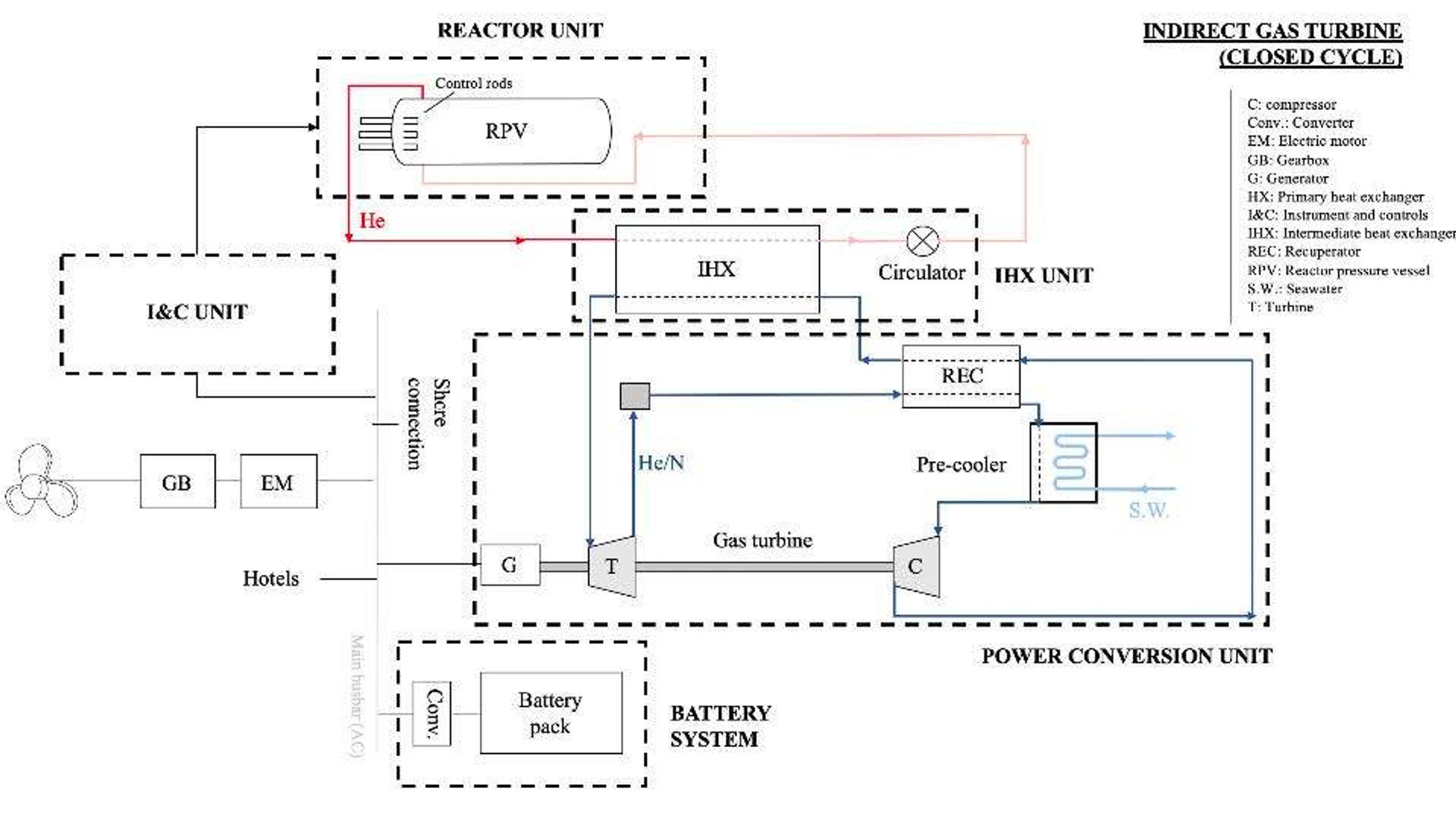

Figure 6: U-Battery system layout, based on [26], [27]
2.4 Shielding
For the reactor installation in the yacht, aspects related to weights and volumes, and radiations are to be addressed. The main component to consider for the mentioned aspects is the reactor’s shielding. The shielding is the main contributor to the system’s weight and volume [26]. The shielding prevents that radiations reach people onboard or in the vicinity of the yacht. Generally, it concerns neutron and gamma radiations only, since alpha particles and beta rays have low penetration [29]. An illustration of the penetrating power and related shielding materials is given in Figure 7. The shield would consist of a first layer which partially absorbs neutrons and a second layer which shields the remaining neutrons and gamma rays [26], [29]. In this analysis various materials (i.e. concrete, PCTFE, PMP) were considered as material of the first layer while lead forms the outer layer. It results that the reactor is completely enclosed within the shield. Openings are not further detailed in this study.
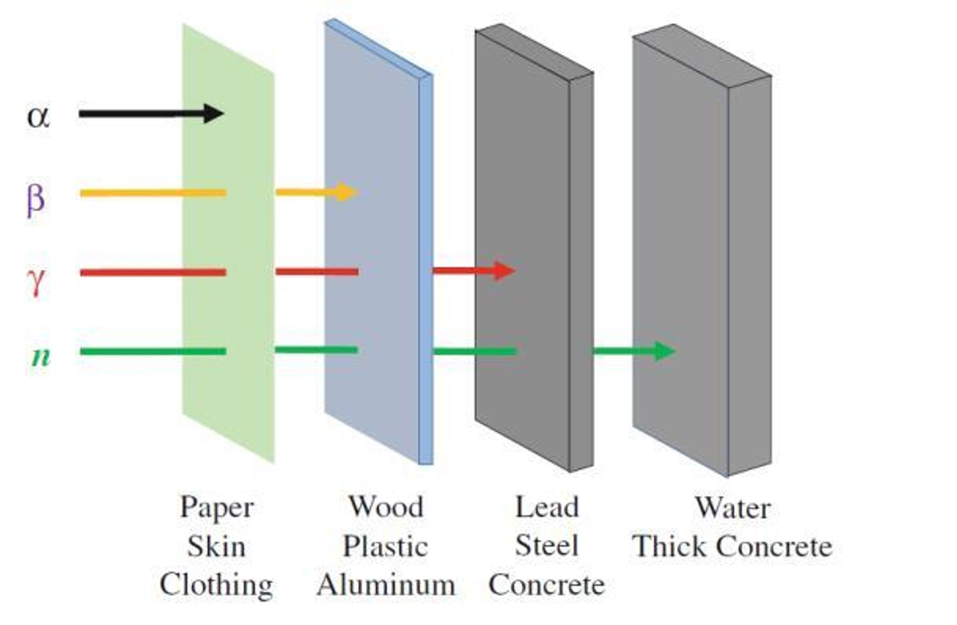

Figure 7: Radioactivity and penetrating power of nuclear radiation [1]
The dimensions and weight calculation of the shielding is not a trivial matter. For this, the removal-attenuation method and the point kernel methods were used as reported in appendix 7.5, following similar considerations on heavy-duty vessel by [26]. The shield’s thickness is determined based on the source of radiation and the maximum allowed dose outside the shield. For the latter aspect, the maximum allowed dose is 50 mSv/year and 1 mSv/year for operators and general public respectively. This difference lies in the equipment and time management procedures used by operators when working in proximity to the reactor [30], [31]. For a yacht, both crew and guests can be considered as general public, as no extra protection for radiation is envisaged. Operational freedom is required for a superyacht application and therefore it is to be considered that the superyacht could be stationary in close proximity to general public for a prolonged period of time. On this basis, a maximum allowed dose of 1 mSv/year is assumed.
2.5 Shipboard (superyacht) concept
The main system proportions (weight and volume) are calculated according to the formulations and references listed in the appendix 7.5. System sizing is proportional to both operational and system requirements, and radiation shielding material. In this study a range of realistic variations is considered to determine a conservative and progressive system sizing which is consequently projected on the yacht concept.
Considered variations and reasoning are:
- Neutron shielding material. The most common and low-cost concrete shielding is considered as well as more advanced and higher cost polymers, being polychlorotrifluoroethylene (PCTFE) and polymethylpentene (PMP) based on removal cross section data published by [32]. These materials are not used yet for this application. Hence, their utilization for shipboard applications remains unexplored.
- Fuel lifetime. Given the load profile and installed power, the reactor core volume is dependent on the fuel lifetime. This indicates the time before the fuel is depleted, hence when refuelling is required. This largely influences system size, weight and operations. Consequently, fuel lifetime is varied from 10 to 30 years to assess its impact.
- Radiation dose. Based on considerations discussed in section 3.4, the tolerable limit for a superyacht application is set at 1 mSv/year. However, time spent onboard and the actual distance from the shield (system outer boundary) remains arbitrary. The most conservative approach considered is a permanent exposure being right next to the system, whilst the most progressive approach considered a mean distance of 10 meters for 40% of all time. The acceptable approach for various parties (owner, yard and legislator) involved is yet to be seen.
Based on these variations, the overall system weight estimations are presented in Figure 8. The figure shows the overall weight of the entire nuclear power system for a relevant power range between 2 and 32 MWe (electrical power output). Lines indicate a system concept design for a combination of variables listed above, grouped for both concrete and PMP neutron shields. Further variations are not explicitly nuanced here. The upper boundary can be seen as the most conservative concept, while the lower boundary as the most progressive one. These two boundaries are further referred to in the yacht design concept study.
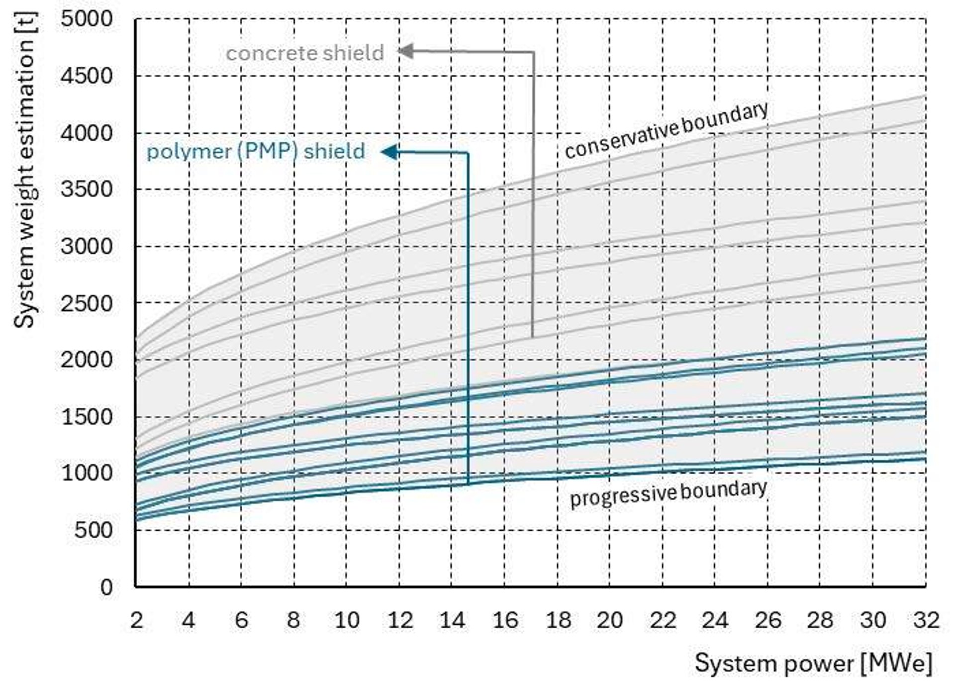

Figure 8: System weight estimation for various operational and system variations
The complete system weight is about half affected by the neutron shield (i.e. concrete) and for the rest by the gamma radiation shield (i.e. lead). When using the PMP as neutron shield, the impact of the lead 𝛾-radiation shield rises to 75-80%. The mean density of the system varies to some extent in relation to the system power and fuel lifetime but is rather constant, being 3 t/m3 for the progressive lower boundary and 4 t/m3 for the conservative upper boundary.
A high-level system sizing study was conducted for the superyacht application. The basis for the study are design trends derived for a fleet of existing Feadship superyachts and projects/designs under development. The installed power trend presented in Figure 2: is the starting point. System proportions are presented as a ratio of the displacement and carene volume of the yacht designs as function of yacht size expressed in gross tonnage (GT), as in Figure 9. The power level for this study is proportional to the displacement increase, since the system weight increase is quite extreme. The influence of the gross tonnage growth is not compensated for, therefore the shown trends illustrate the impact on the system proportions to the original yacht size expressed by GT.
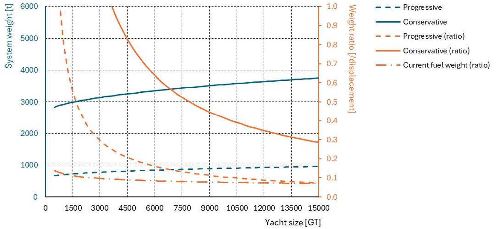

Figure 9: Relative power system proportions as function of yacht size
It can be concluded that the weight and volume penalty is very large for small-to-medium superyachts, i.e. between 500 and 3000 GT, ranging from +30% of the displacement for a progressive nuclear system design for 3000 GT up to +100% in displacement for a conservative design for a 3500 GT vessel, and substantially more for smaller yachts. In comparison to the current fuel and power system weight, it requires a large increase in hull displacement and overall volume of the vessel. However, the volume penalty is comparatively smaller (factor 3 to 4) due to the relative high density of the nuclear system. Although arbitrary, it is considered that a weight increase of 25% is judged viable. This considering the impact in terms of yacht size and related system scaling (e.g. casco structure, mooring, propulsion etcetera), excluding costs. This results in yachts from 3000 GT and above being feasible to accommodate a progressive nuclear power system. For the more conservative power system a very large yacht of around 15000 GT could be viable. This general conclusion that nuclear power systems may only work for large vessels, supports the findings of [26], the latter considering investigations on various merchant ship concepts.
Besides the reactor core, the neutron- and gamma-radiation shields govern primarily the overall weight and size of the system. Other main components of the nuclear plan include the items indicated in the schematics (Figure 5, Figure 6). The ventilation flow in and out the vessel is not further detailed in the current study. In Figure 10, a relevant power system under consideration is shown which is further used for a concept application.
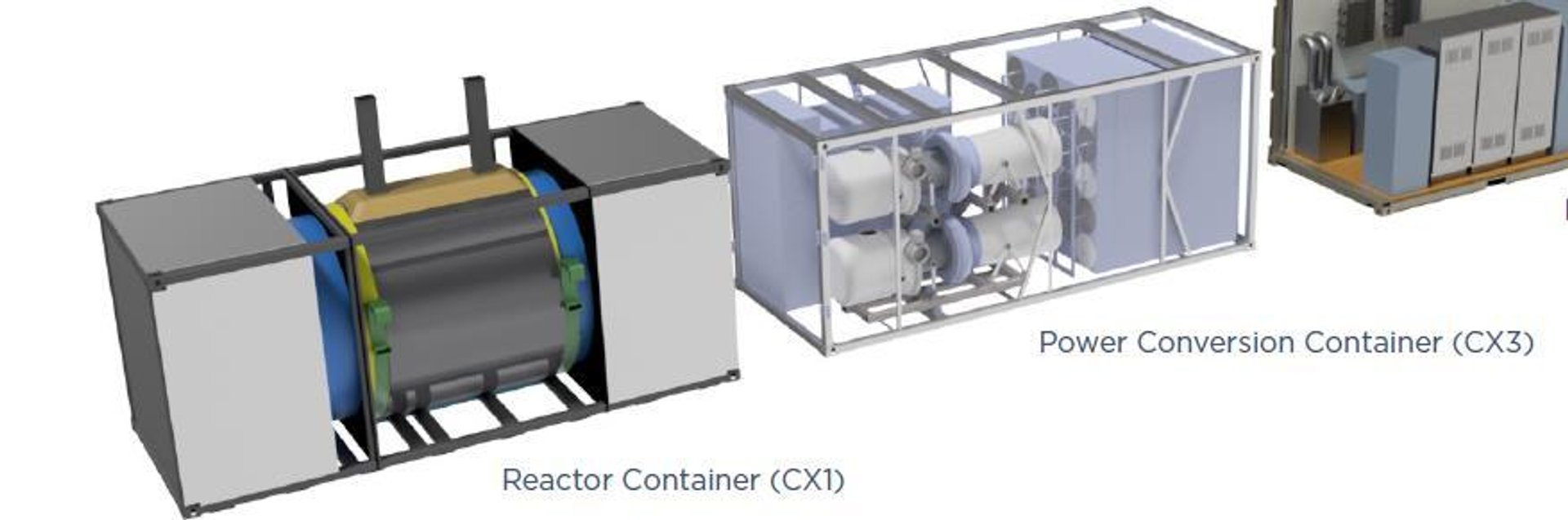

Figure 10: Heatpipe reactor system, 5MWe eVinciTM system, 2x20ft containers Courtesy of Westinghouse
The overall system dimensions could be derived. This by adding the shielding system, scaling the system with a maximum power of 8MWe for a 30 year fuel lifetime, PMP neutron shield and a radiation dose related to permanent exposure at the outer boundary of the lead-shield. The resulting dimensions are given in Figure 11.
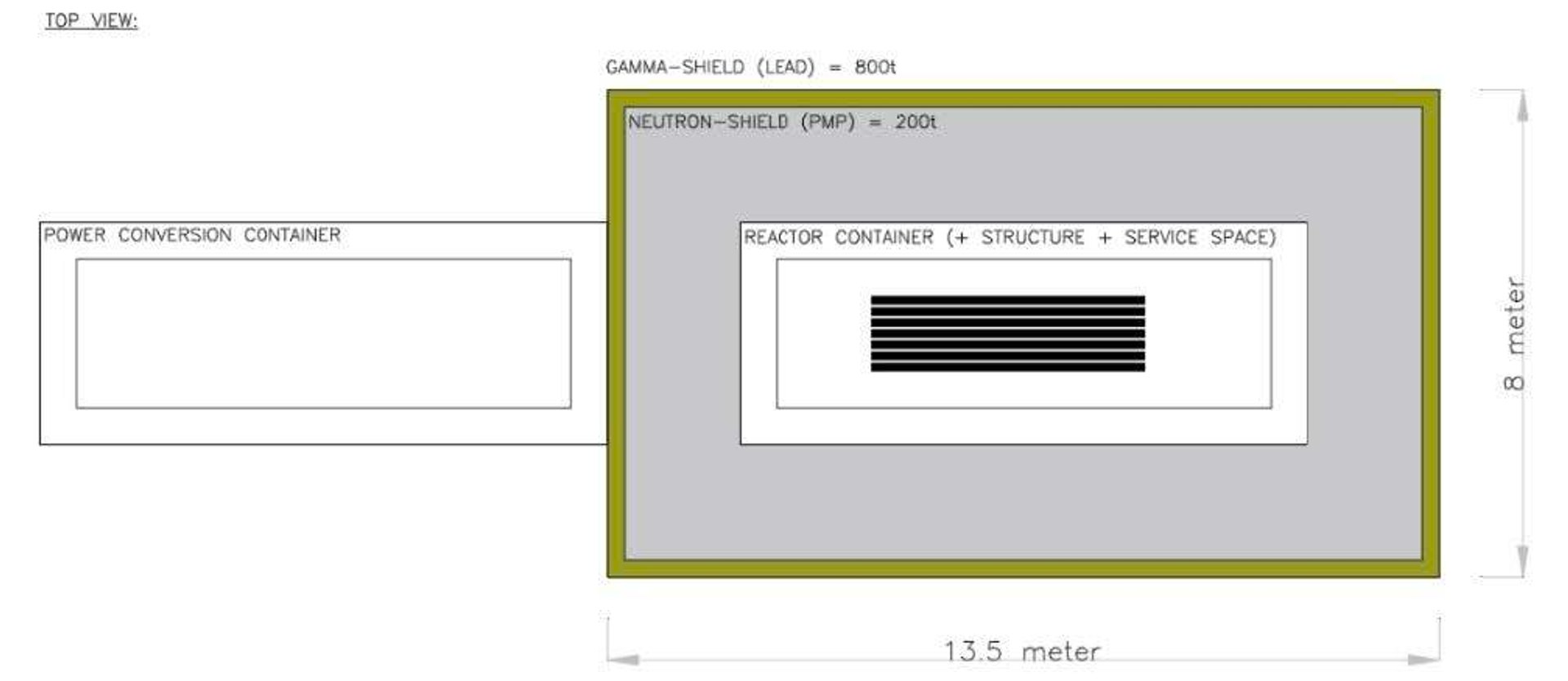

Figure 11: 8 MWe scaled version of the Westinghouse system with shielding
The portrayed system of Figure 11 was illustrated in a 4500 GT yacht general arrangement. This is depicted in Figure 12. It results that the installation of a nuclear system in a relevant yacht power-wise is challenging. The displacement increase will be in the order of 25% and it is judged feasible, but the interior volume will need to be re-distributed. As suggested by the high-level study (see Figure 9), in this yacht size range, installation of a nuclear power system is considered feasible from a technical-concept point of view. Principles for refuelling procedure and integration in the design will have to be determined, and therefore a 30-year fuel life is opted for. Probably, a float-over, lift-in/-out process through a bottom access arrangement could be viable to exchange the reactor container. Although, strength considerations associated to the large and dense weight in way of a bottom access are judged challenging to overcome.
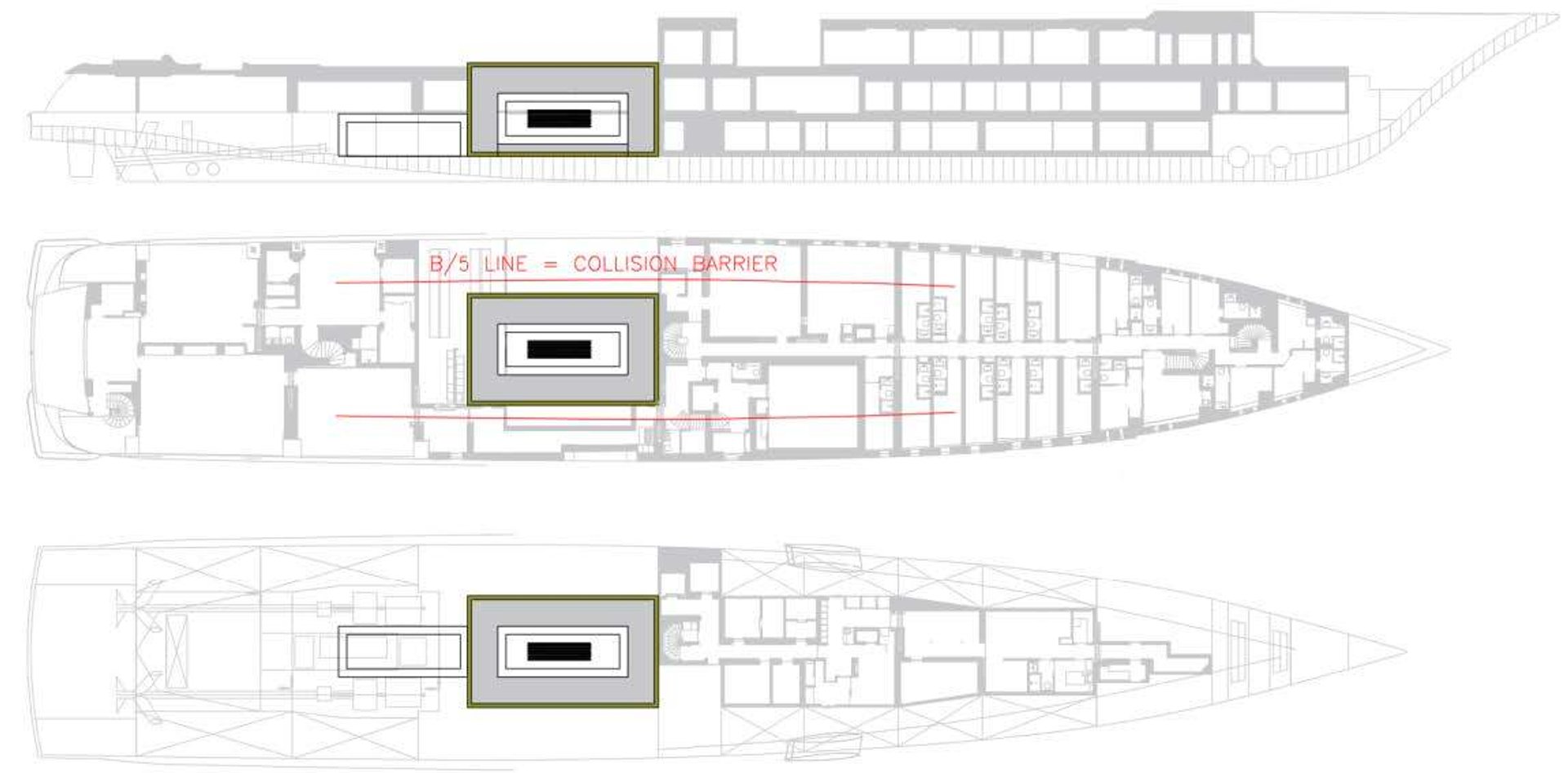

Figure 12: 4500GT Feadship with 8 MWe power 30 year fuel life (re-design required)
3. Legislation
Licensing is challenging for any nuclear system trade. This relates to trade agreements between countries and liability of individual nations for private companies and individuals. Not only the first ultimate beneficial owner, but also after future re-sale. The latter is particularly relevant for modular and mobile small/micro reactor technology.
In the maritime sector the design of nuclear-propelled commercial ships is covered by the IMO Resolution A.491-XII of 1981 issued in concomitance with the IAEA [33]. However current code only applies to pressurized water reactors (PWRs) [26], [33]. Furthermore, in accordance with the UNCLOS nuclear-powered ships are treated equally as all other ships in terms of sailing in international sea area. However, a specific country may regulate nuclear-propelled ships in their national zones [26], [34]. International cooperation is coordinated through the Nuclear Energy Maritime Organization [35].
Furthermore, some concerns can arise linked to criminal activities, terrorism and piracy for private-owned vessels frequently subjected to change of property or chartering. These can cause weaponization of fissile material (radioactive waste) and operational disruption. This can be avoided by deploying LEU. A design with HEU (enrichment above 90%) in fact carries the risk of diversion for weapons-usable material. Thanks to the Treat on the Non-Proliferation of Nuclear Weapons (NPT) of 1968, the designs using HEU as fuel are not spread among non-authorized persons, organizations and countries [1], [26]. Increase of proliferation resistance is foreseen in future technologies such as the already mentioned generation IV reactors and MMRs. A long fuel cycle technology would be preferred. Additionally, it can be expected that cybersecurity will play an important role in this matter. A security framework has to be issued by international bodies such as IMO and IAEA. This would be also needed for extensive training for personnel onboard during operations and in shipyards.
Various other challenging legislation aspects are to be considered but not further discussed here, e.g. high pressure gas systems, navigating special protective sea areas and others.
4. Conclusions and recommendations
The following main conclusions can be drawn from the presented work considering the application of nuclear power onboard of superyachts or as a source of production of power-to-x fuels:
- Micro-modular-reactors such as the high-temperature gas-cooled reactors or heatpipe reactors are the best fit for the power requirements of a broad size range of superyachts.
- The trade-off between using onboard nuclear power systems and grid-based nuclear power producing methanol (power-to-x) fuel, showed that the latter process would require around 8 times the amount of nuclear material.
- The neutron and gamma radiation shielding systems are sized for various shielding materials and yet arbitrary operational variables. It resulted that systems have a significant impact on the overall weight of the yacht, rendering it feasible considering a progressive approach, for yachts of 3000 GT and above. This, however, still impacts the overall size of the vessel, depending on the final nuclear power system and risk profiles adopted.
- Licensing, liability and overall regulatory pathways do not exist yet to apply nuclear power systems onboard a superyacht. Promising international collaborations are in progress, potentially unlocking future applications.
Recommendations:
- In the current study the direct and indirect costs are not considered. Further research on this is judged crucial. It is to be considered that the power utilisation of a nuclear system onboard a superyacht will be very low, accounting for about 5-10% annual time, whereas installing the same nuclear system on for grid powering purposes this utilisation factor can extend to 100%. This is to be further investigated considering the system’s return on investment.
- The study shows great dependency on system specifications, namely the shielding composition. Further investigations on technical readiness and development steps are important to optimize the system design, specifically the shielding. Suggestion is to optimize for alternative materials to concrete, such as polymers and fibers.
- Additionally, to further optimize the shielding, bottom section of the shielding and the refuelling arrangement are to be further studied depending on various operational scenario’s and the received radiation dose of workers and technical structural solutions.